Why Do Heavy Industries Rely on Specialized Pump High Pressure Low Flow Systems?
In industrial fluid dynamics, achieving high discharge pressures while maintaining precise, low volumetric flow rates presents a unique set of mechanical challenges. Standard centrifugal pumping systems, which excel at moving large volumes of liquid at moderate pressures, are inherently inefficient when operated under low specific speed conditions. When a process demands high system head coupled with restricted flow, specialized pump high pressure low flow designs become necessary to maintain operational efficiency and equipment longevity.
United Power specializes in the engineering of robust fluid-handling machinery designed to operate reliably under these severe parameters. This analysis examines the fluid mechanics, design configurations, and system-level challenges associated with low-flow, high-pressure operations, providing procurement managers and process engineers with the insight required to make informed equipment selections.
The Fluid Dynamics of Low Specific Speed Applications
To understand why standard pumps fail in high-pressure, low-flow scenarios, one must examine the dimensionless parameter known as specific speed. Specific speed defines the geometric characteristics of a pump impeller based on rotational speed, flow rate, and total dynamic head. When the flow rate is low and the head requirement is high, the resulting specific speed value is exceptionally small.
In radial-flow centrifugal designs, a very low specific speed requires an impeller with a large outer diameter relative to a narrow eye width. This geometry leads to substantial disk friction losses, as the liquid is sheared within the tight clearances between the rotating impeller and the stationary casing. Internal recirculation also increases significantly under these conditions, causing hydraulic instability, pressure pulsations, and rapid temperature spikes within the fluid chamber.
Consequently, positive displacement designs or highly specialized kinetic designs are selected for these applications. Unlike kinetic pumps that rely on fluid velocity to generate pressure, positive displacement systems physically isolate a fixed volume of fluid and force it into the discharge line, ensuring consistent flow rates regardless of downstream pressure changes.
Mechanical Configurations for High Pressure and Low Flow
To meet the demands of these specialized operations, manufacturers utilize several distinct mechanical designs, each suited to specific process environments and fluid characteristics.
Reciprocating Plunger Systems
Reciprocating plunger designs are highly efficient mechanisms for achieving extreme pressures at minimal flow rates. These units operate via a crankshaft that drives a solid cylindrical plunger back and forth inside a high-pressure cylinder. As the plunger retracts, the inlet check valve opens, drawing fluid into the chamber. As it advances, the inlet valve seals, and the discharge check valve opens, expelling the fluid.
High Volumetric Efficiency: Because the clearance space within the liquid end is minimized, internal slip is nearly non-existent, allowing for volumetric efficiencies often exceeding 90%.
Pressure Capability: These systems can easily generate pressures exceeding several hundred bar while handling flow rates of just a few liters per hour.
Sealing Mechanisms: Packing rings, stuffing boxes, and specialized barrier fluids prevent process fluid leakage and protect the reciprocating shaft from premature wear.
Hydraulically Actuated Diaphragm Systems
When handling hazardous, corrosive, or toxic fluids, the absolute containment of the pumped medium is paramount. Hydraulically actuated diaphragm designs utilize a flexible, chemically inert barrier to completely isolate the process fluid from the reciprocating mechanical drive components. A plunger acts on a reservoir of hydraulic fluid, which in turn deflects the diaphragm back and forth to displace the process fluid.
Hermetic Sealing: The lack of dynamic seals exposed to the external environment eliminates leak paths, protecting personnel and surrounding infrastructure.
Double-Diaphragm Integrity: Multi-layered diaphragms equipped with pressure-sensing leak detection systems provide an alert if the primary barrier fails, preventing process contamination.
Overpressure Protection: Integrated hydraulic relief valves prevent system damage in the event of a downstream line blockage.
Regenerative Turbine Designs
For applications where positive displacement is undesirable due to pulsation issues, regenerative turbine systems offer a continuous, non-pulsating flow at elevated pressures. These pumps feature a double-sided impeller with numerous small, radial vanes machined around its periphery. The fluid enters the impeller channel and is repeatedly recirculated between the impeller vanes and the casing channel, continuously building pressure through regenerative momentum transfer.
Smooth Discharge Profile: Unlike reciprocating designs, regenerative turbines provide a continuous, pulseless flow.
Self-Venting Capability: The rapid mixing action allows these units to handle entrained gases without vapor locking, which is a frequent issue in standard centrifugal pumps.
Compact Footprint: They offer a space-saving alternative to multi-stage centrifugal systems for low-flow, high-pressure duties.
Overcoming Key Operational Challenges
Deploying a pump high pressure low flow configuration requires careful consideration of several mechanical and thermodynamic factors that do not typically affect low-pressure or high-flow systems.
Pulsation control is a primary concern in reciprocating positive displacement installations. The cyclic nature of plunger movement generates pressure waves that can cause severe vibration in connected piping networks, leading to joint fatigue, flange leaks, and valve failures. To mitigate this, United Power integrates gas-charged pulsation dampeners close to the pump discharge manifold. These accumulators absorb the energy peaks of each stroke, smoothing the flow profile and stabilizing downstream pressure.
Another major challenge is heat dissipation. At low flow rates, the volume of fluid passing through the pump is insufficient to carry away the heat generated by friction and hydraulic inefficiencies. This can lead to rapid thermal expansion of internal components, packing degradation, and fluid vaporization. To prevent thermal damage, systems should be designed with an automatic recirculation valve or a continuous bypass loop that directs a portion of the flow back to the suction tank, ensuring a continuous minimum flow rate is maintained through the pump body.
Material wear is also accelerated at high pressures. High fluid velocities across valve seats and plunger surfaces can lead to erosion-corrosion, especially when handling abrasive micro-particles. United Power addresses this by using wear-resistant materials such as solid ceramic plungers, tungsten carbide valve seats, and super duplex stainless steel for fluid end components. This ensures prolonged component life and reduces maintenance intervals.
Selecting the Appropriate System for Industrial Operations
Choosing the correct equipment requires a meticulous review of the operational parameters and fluid characteristics. Engineers must calculate the Net Positive Suction Head Available (NPSHa) to ensure it exceeds the Net Positive Suction Head Required (NPSHr) by the pump. Because high-pressure pumps often require positive inlet pressures to prevent cavitation, suction piping must be designed to minimize friction losses, incorporating straight runs and large-diameter pipes where possible.
Fluid viscosity also influences the choice of pump. High-viscosity liquids increase resistance within positive displacement valves, requiring slower stroke speeds and larger valve clearances to prevent incomplete chamber filling. Conversely, very low viscosity liquids increase the potential for slip in positive displacement designs, requiring high-precision clearances to maintain consistent output.
Finally, driver selection must match the load profile. High-pressure pumps require high starting torque, particularly under full system pressure. Employing variable frequency drives allows operators to adjust the flow rate precisely by changing the motor speed while maintaining the necessary torque across the entire operating range.
B2B Collaboration and Procurement Solutions
Selecting and implementing a pump high pressure low flow system is a complex engineering task that requires close cooperation between the end-user and the equipment manufacturer. Off-the-shelf solutions rarely meet the precise demands of specialized industrial processes, making custom configuration a necessity for long-term system reliability.
United Power works directly with plant managers, process engineers, and procurement teams to deliver tailor-made pumping systems. Our engineering department evaluates fluid properties, piping designs, and pressure specifications to manufacture skid-mounted packages complete with control panels, pulsation dampeners, and safety bypass valves. If your facility requires robust, high-pressure fluid handling machinery engineered to withstand rigorous duty cycles, please contact the United Power sales and engineering division to submit your design specifications and request a formal inquiry.
Frequently Asked Questions
Q1: What is the primary difference between a high-pressure low-flow centrifugal pump and a positive displacement pump?
A1: Centrifugal pumps rely on dynamic kinetic energy to generate head, which drops in efficiency and becomes unstable at very low flows. Positive displacement pumps isolate fixed volumes of fluid mechanically, ensuring that the flow rate remains relatively constant even as the discharge pressure increases, making them highly efficient for low-flow, high-pressure duties.
Q2: How does fluid viscosity affect the performance of a pump high pressure low flow system?
A2: High viscosity increases flow resistance through the internal valves and ports, which can lead to incomplete chamber filling and cavitation if the pump is operated at excessive speeds. Low viscosity fluid increases the likelihood of internal slip (internal leakage), which reduces the overall volumetric efficiency of positive displacement configurations.
Q3: Why is a pulsation dampener necessary in reciprocating high-pressure systems?
A3: Reciprocating plungers generate discontinuous fluid velocity, creating pressure spikes with each stroke. A pulsation dampener absorbs these pressure fluctuations, preventing hydraulic shock, minimizing piping system vibration, and protecting sensitive downstream instrumentation from fatigue damage.
Q4: How do you prevent overheating in a low-flow pumping system?
A4: Overheating is prevented by installing a minimum flow bypass loop. Since the low volume of process fluid cannot absorb all the mechanical heat generated during operation, the bypass line continuously diverts a portion of the fluid back to the supply source, ensuring sufficient liquid passes through the pump to maintain thermal equilibrium.
Q5: What materials are typically used for the fluid ends of high-pressure pumps handling corrosive media?
A5: For corrosive or abrasive applications, fluid ends are manufactured from premium alloys such as 316L stainless steel, duplex, or super duplex stainless steel. Internal wear parts, like plungers and valve trim, often utilize industrial ceramics, tungsten carbide, or satellite coatings to resist erosion-corrosion.
_173829.webp "Selecting the Right 0.75 kw Water Pump: An Engineering and Performance Analysis")
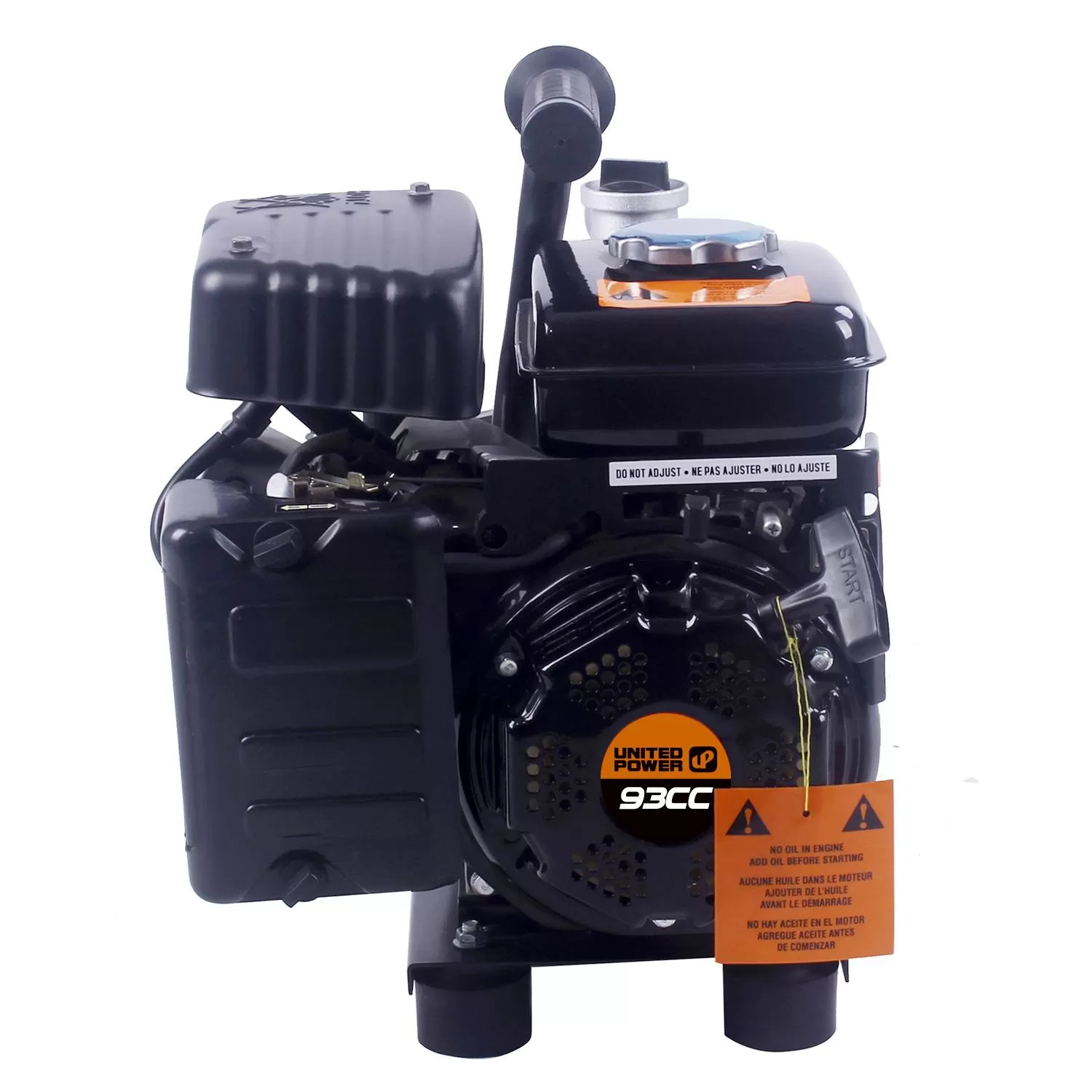
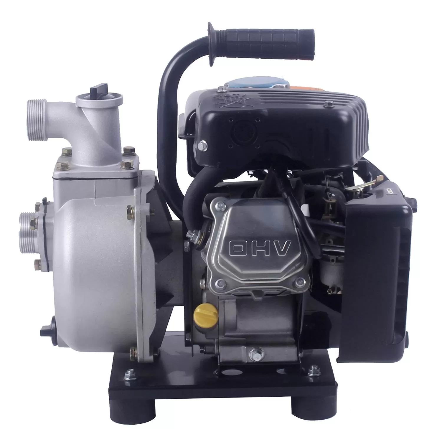
.webp "Why Do Heavy Industries Rely on Specialized Pump High Pressure Low Flow Systems?")
.webp "4 Parameters for Evaluating a Water Pipe Line Cleaning Pump")
