Engineering Guide to Sizing and Deploying a 10 kW Generator 3 Phase System
Three-phase power distribution serves as the global standard for industrial equipment, commercial facilities, and severe-duty remote installations. While high-megawatt gensets dominate utility infrastructure, lower-capacity segments encounter unique mechanical and electrical stresses. Selecting, commissioning, and maintaining a 10 kw generator 3 phase requires precise engineering analysis. These systems must deliver continuous power stability while managing inductive motor inrush currents, harmonic distortions, and unevenly distributed line loads within a compact physical footprint.
Electrical engineers, facility directors, and fleet procurement managers frequently deploy this rating to support auxiliary utilities, mobile pumping units, telecom base transceiver stations, and remote field camps. Because standard three-phase systems are configured around balanced loads, scaling down to a ten-kilowatt nominal output creates tight margins for phase-angle displacement and thermal tolerance. Proper equipment selection hinges on understanding electromechanical component integration, international performance standards, and real-world duty cycles.
.webp?t=1789024808658 "10 kw generator 3 phase")
Electromechanical Architecture and Generating Principles
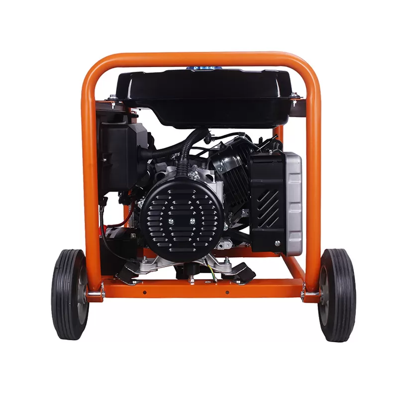
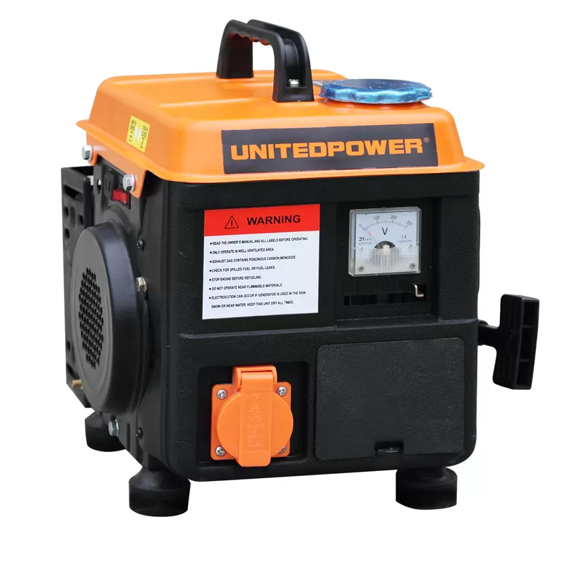
A functional power generating set integrates an internal combustion prime mover, a synchronous brushless alternator, an automated voltage regulation network, and a structural base frame. In a 10 kW three-phase unit, every component must operate under strict governor and excitation parameters to sustain sinusoidal output under variable loads.
Alternator Topology and Winding Configurations
The alternator transforms mechanical rotational energy into multi-phase alternating current through electromagnetic induction. Standard industrial units utilize four-pole synchronous designs operating at 1,500 RPM for 50 Hz grids or 1,800 RPM for 60 Hz infrastructure. Brushless exciter mechanisms with rotating rectifier assemblies have superseded traditional slip-ring configurations, eliminating carbon dust accumulation and lowering routine servicing overhead.
Winding pitch is an essential technical variable. A 2/3 pitch design minimizes the third, ninth, and fifteenth harmonic components (triplen harmonics) along the neutral conductor. When non-linear electrical components like variable frequency drives (VFDs) or switch-mode power supplies draw current in pulses, proper winding pitch prevents neutral conductor overheating and preserves power quality. The physical stator stack should feature Class H thermal insulation, impregnated with high-grade epoxy resins to tolerate continuous operating temperatures up to 180 degrees Celsius.
Excitation Systems and Voltage Regulation
Modern alternators in this power class utilize either shunt-fed excitation or auxiliary winding networks paired with solid-state Automatic Voltage Regulators (AVR). Shunt systems derive power directly from the main stator terminals, rendering them susceptible to voltage collapse during heavy short-circuits or direct-on-line (DOL) electric motor starts. Auxiliary winding circuits and permanent magnet generator (PMG) excitation isolate the AVR's power supply from output distortions, maintaining magnetic field excitation even when starting large motor loads.
Digital AVRs provide tight steady-state voltage regulation, typically within plus or minus 0.5 to 1.0 percent across no-load to full-load shifts. These regulators incorporate under-frequency roll-off (UFRO) protection circuits. When a sudden mechanical step-load depresses engine speed, the AVR reduces output voltage proportionally, allowing the engine to recover torque without stalling.
Sizing and Load Dynamics for a 10 kW Generator 3 Phase
Matching generating assets to operational profiles requires distinguishing between real power (kilowatts) and apparent power (kilovolt-amperes). In three-phase topologies, output ratings are established using a lagging power factor of 0.8.
Apparent Power Formulation: S (kVA) = P (kW) / 0.8
Nominal Capacity: A 10 kW prime-rated unit corresponds precisely to 12.5 kVA.
Full-Load Phase Current Calculation at 400V (50 Hz): I = (12,500 VA) / (1.732 x 400 V) = 18.04 Amperes per phase.
Full-Load Phase Current Calculation at 208V (60 Hz): I = (12,500 VA) / (1.732 x 208 V) = 34.69 Amperes per phase.
Procurement teams must not assume this full capacity is universally accessible across any wiring configuration. Deploying a 10 kw generator 3 phase to power single-phase auxiliary branch circuits exposes the system to thermal unbalance risks.
ISO 8528 Rating Classifications
International standard ISO 8528 establishes four discrete operational envelopes for reciprocating internal combustion engine driven alternating current generating sets:
Continuous Operating Power (COP): Unlimited running hours under constant, unvarying mechanical load. Standard practice derates continuous output to 70-80 percent of nominal value.
Prime Rated Power (PRP): Variable operational loads for unlimited cumulative operating hours per year. A 10 percent overload capability is typically permissible for one hour within every twelve hours of continuous runtime.
Emergency Standby Power (ESP): Maximum power output available during utility outages or testing cycles, limited to a fixed number of annual run hours without permissible overload capacity.
Data Center Continuous (DCC): Specialized continuous ratings often deployed in mission-critical IT hubs, rarely applicable to the 10 kW segment.
Inductive Motor Starting and Transient Response
Electric motors exhibit locked-rotor conditions during startup, drawing five to seven times their normal running amperage. This massive current draw induces momentary voltage sag and frequency deviation across the generator set. If an operations site requires starting a 4 kW three-phase induction motor across-the-line, the instantaneous starting demand can reach 20 to 28 kVA.
Without sufficient alternator subtransient reactance (X"d) control, the resulting voltage drop can de-energize external magnetic contactors or cause the genset control unit to trip on an under-voltage fault. Implementing soft starters, variable frequency drives, or star-delta transition contactors reduces starting demand, bringing inductive surges well within the alternator's transient recovery envelope.
Critical Engineering Challenges and Mitigation
Operating lower-kilowatt multi-phase equipment introduces distinct site hurdles that do not manifest as severely in large megawatt installations.
Phase Current Unbalance and Neutral Heating
An unbalanced electrical load occurs when individual phases draw unequal currents. In severe conditions, this creates an unequal magnetic field inside the stator, inducing eddy currents in the rotor forging and damper cage windings. The physical result is localized overheating, winding insulation failure, and negative-sequence voltage components that degrade connected three-phase motors.
Neutral current in a balanced star (wye) circuit equals zero. When loads are unbalanced or polluted by harmonic currents, the neutral conductor carries the vector sum of these unbalances. Facilities must balance branch circuits so that the current variance between any two phases does not exceed 10 to 15 percent. Alternator manufacturers mandate derating total system output if single-phase unbalance exceeds 20 percent of total nameplate rating.
Light Load Operation and Wet Stacking
Diesel engines operating continuously below 30 percent of rated capacity cannot reach proper internal operating temperatures. Low cylinder temperatures lead to incomplete fuel combustion, allowing unburned fuel and carbon particles to accumulate in the exhaust manifold, turbocharger housing, and exhaust piping. This operational fault, known as wet stacking, reduces volumetric efficiency, fouls injector nozzles, and causes oil dilution.
When operating parameters require a 10 kw generator 3 phase to support variable or intermittently low base loads, engineers specify an integrated resistive load bank. Automated controllers monitor continuous power draw; if site demand drops below 35 percent of prime rating, the load bank steps in automatically to maintain engine cylinder temperatures and burn off soot deposits.
Ambient Derating Factors
Operating machinery in non-standard ambient conditions reduces both engine power output and alternator cooling efficiency. Standard factory nameplate data assumes an ambient temperature of 25 degrees Celsius, barometric pressure of 100 kPa, and relative humidity of 30 percent at sea level. High-altitude operations reduce combustion air density, which limits fuel injection rates to prevent black exhaust smoke.
| Operating Parameter | Baseline Threshold | Standard Derating Factor |
|---|---|---|
| Altitude | Above 1,000 meters MSL | 1.0% to 1.5% capacity reduction per additional 100 meters |
| Ambient Temperature | Above 40 degrees Celsius | 2.0% capacity reduction per 5 degrees Celsius increase |
| Winding Insulation Derate | Above 40 degrees Celsius | Alternator capacity reduced by 3.0% to 5.0% for Class H limits |
Mechanical and Canopy Engineering Specifications
Packaged equipment performance relies as much on enclosure engineering, cooling fluid dynamics, and fuel storage as it does on electrical components. When evaluating a 10 kw generator 3 phase, engineering teams must scrutinize the chassis layout for serviceability and environmental protection.
Acoustic Attenuation and Enclosure Dynamics
Deployments in urban, commercial, or residential spaces require sound-attenuated, weather-protective canopies. Sound ratings are measured on a hemispherical array at a distance of 7 meters, with high-performance enclosures dampening operational noise to 65 dB(A) or lower. Achieving this reduction requires multi-stage acoustic baffles, high-density mineral wool sound-absorbing insulation, and low-frequency tuned silencers mounted internally within the hood.
Acoustic attenuation cannot compromise engine cooling. The internal radiator, engine-driven axial fan, and air inlet/outlet louvers must maintain neutral or negative static pressure inside the housing. Designers must evaluate the enclosure's Limiting Ambient Temperature (LAT), ensuring the radiator core rejects sufficient heat when external temperatures reach 45 to 50 degrees Celsius.
Fuel Storage and Engine Subsystems
Sub-base fuel tanks must feature double-wall containment (bunding) holding 110 percent of system fluid capacity to prevent ground contamination from primary tank breaches. In remote telecom and microgrid applications, fuel volume directly determines scheduled maintenance intervals. Daily service tanks must incorporate low-level, high-level, and fuel-leak detection floats wired into the primary safety trip matrix.
The fuel delivery system requires a two-stage process: a primary fuel-water separator filter with transparent drain bowl, followed by a secondary spin-on micro-filter rated between 2 and 5 microns. Water removal protects common-rail and high-pressure mechanical injection pumps from hydraulic cavitation, abrasive wear, and microbial corrosion.
.webp?t=1789024808658 "10 kw generator 3 phase")
Control Automation, Protection, and Synchronization
Contemporary genset controllers use microprocessors to execute real-time automated mains failure (AMF) detection, protection shutdowns, and dynamic system telemetry.
Protection Matrices and Thresholds
The control module constantly samples three-phase line-to-line (V_LL) and line-to-neutral (V_LN) voltages, phase currents, active power, reactive power, power factor, and operational frequency. The primary protection matrix trips the main breaker or shuts the prime mover down under several critical faults:
ANSI 27 / 59 (Under/Over Voltage): Trips if output drifts beyond plus or minus 10 percent of nominal setpoint for more than 1.5 seconds.
ANSI 81O / 81U (Over/Under Frequency): Protects inductive equipment from core saturation during engine speed drop.
ANSI 51 (Phase Overcurrent): Employs inverse-time delay curves to clear external electrical faults without damaging the alternator stator.
ANSI 46 (Negative Phase Sequence / Current Unbalance): Disconnects output if current unbalance exceeds tolerable limits for extended periods.
ANSI 32R (Reverse Power Protection): Halts the engine if electrical power flows backward from the bus into the alternator during parallel operations.
For custom industrial projects, United Power configures control architectures with programmable input/output logic to coordinate generator behavior with site fire suppression relays, seismic trip switches, and remote supervisory monitoring stations.
Integration with Automatic Transfer Switches (ATS)
An Automatic Transfer Switch routes power between the primary utility feed and the generating set. The ATS monitors utility voltage balance. If grid voltage collapses, drops below 80 percent, or experiences open-phase conditions on any line, the ATS logic triggers the genset start contacts via a two-wire interface.
Mechanical and electrical interlocks prevent back-feeding local generation onto dead utility distribution lines, protecting line workers down-grid. Modern transition designs utilize open-transition (break-before-make) contactors with adjustable in-phase monitoring, or closed-transition (make-before-break) systems where momentary paralleling prevents power interruptions during scheduled switchovers.
Procurement and Specification Matrix
Procurement teams must outline distinct technical boundaries to eliminate low-tier consumer equipment that cannot handle industrial duties. Application engineering support from United Power assists system designers in translating mechanical torque, cooling margins, and dynamic step-loading criteria into actionable equipment tenders.
| Technical Specification | Light Duty / Residential Standard | Heavy Industrial / Prime Duty Standard |
|---|---|---|
| Engine Operating Speed | 3,000 / 3,600 RPM (2-pole) | 1,500 / 1,800 RPM (4-pole, liquid-cooled) |
| Alternator Cooling & Build | Open drip-proof, brush-type | Brushless, auxiliary winding or PMG, Class H |
| Total Harmonic Distortion (THD) | Up to 15% to 20% | Under 5% linear; under 3% individual harmonic |
| Base Frame Construction | Pressed light-gauge steel | Heavy structural channel with integrated 110% bunding |
| Governor System | Mechanical flyweight (+/- 5% droop) | Isochronous electronic governor (+/- 0.25% steady state) |
| Breaker Topology | Standard thermal-magnetic trip | Motorized MCCB with adjustable LSI trip parameters |
Installation, Commissioning, and Maintenance Protocols
System life expectancy depends on proper installation engineering and disciplined preventive maintenance. Bypassing mechanical foundation rules or skipping fluid sampling will shorten equipment life regardless of component quality.
Rigging, Foundation, and Isolation
The unit must rest on a reinforced concrete housekeeping pad. The foundation mass should ideally equal 1.5 times the wet weight of the complete genset package to absorb mechanical vibration and counteract operational resonance. Neoprene-in-shear or steel spring anti-vibration mounts (AVMs) isolate the structural sub-base from the foundation pad.
Exhaust systems require stainless steel bellows expansion joints installed directly at the engine exhaust manifold outlet. These joints isolate the engine block from thermal expansion stresses and dead exhaust pipe weight. Exhaust runs must slope slightly away from the engine toward a low-point condensation trap to prevent acidic moisture from draining into exhaust valves.
Scheduled Preventative Maintenance Intervals
Operating teams must execute preventive maintenance according to actual running hours and chronological time metrics:
Daily / Weekly Checks: Inspect oil level, coolant level, fuel sediment traps, battery electrolyte charge voltage, and air inlet restrictions. Verify engine block heater functionality (standard units maintain water jacket temperature at 40 degrees Celsius for fast starts).
250-Hour / 6-Month Protocol: Change engine crankcase oil and spin-on lube filters. Clean or replace fuel pre-filters. Verify fan belt tension and battery terminal torque.
500-Hour / Annual Protocol: Replace main fuel filter elements, air cleaner cartridges, and cooling system conditioning filters. Conduct insulation resistance testing (megger test) on stator and exciter windings at 500V DC; reading must exceed 5 Megohms.
Load Bank Testing: Subject the genset to an artificial resistive load bank for two hours annually at 100 percent of nameplate PRP to burn out wet-stack deposits and verify cooling performance under peak thermal loads.
Lifecycle Cost Analysis and Value Dynamics
Procuring low-capacity multi-phase generation assets based solely on initial purchase price frequently increases life-cycle costs. Operating expenses over a typical ten-year equipment life span routinely eclipse the initial capital investment.
The lifecycle performance of a 10 kw generator 3 phase hinges on fuel economy, mean time between overhauls (MTBO), and spare-parts availability. Low-speed (1,500/1,800 RPM) industrial power blocks feature major overhaul cycles exceeding 15,000 to 20,000 operating hours when maintained within OEM fluid contamination parameters. High-speed alternatives running at 3,000/3,600 RPM often require top-end overhauls before reaching 3,000 hours.
Calculating operational expenditures requires reviewing specific fuel consumption curves (SFOC). Typical diesel consumption for an industrial prime-rated unit at this output tier follows a predictable trajectory:
50% Load: Approximately 1.6 to 1.8 liters per hour
75% Load: Approximately 2.2 to 2.5 liters per hour
100% Load: Approximately 3.0 to 3.4 liters per hour
Selecting units with isochronous electronic engine governing maintains precise fuel metering across variable electrical demand, lowering annual fuel consumption by 4 to 7 percent compared to mechanical governor assemblies.
Frequently Asked Questions
Q1: Can a 10 kW generator 3 phase run single-phase equipment safely?
A1: Yes, by connecting loads between any single line phase and the neutral conductor (line-to-neutral configuration). However, aggregate single-phase loads must be distributed evenly across all three phases (L1, L2, and L3). Current unbalance between any two phases should not exceed 10 to 15 percent. Drawing the full 10 kW capacity exclusively across one phase will overheat that specific stator winding, induce destructive harmonic voltages, trip the thermal overload protection, and void equipment warranties.
Q2: Why is the active power rated at 10 kW while the apparent power is rated at 12.5 kVA?
A2: Three-phase industrial alternating current systems operate with an assumed standard load power factor of 0.8 lagging. Apparent power represents the product of total root-mean-square voltage and current, whereas active power represents the real work performed by the equipment. Dividing active power (10 kW) by the 0.8 power factor yields an apparent power rating of 12.5 kVA. Sizing calculations must incorporate apparent power to ensure alternator windings and switchgear are not overloaded by inductive currents.
Q3: What are the engineering consequences of running this equipment continuously under light loads?
A3: Sustained operation below 30 percent of prime capacity prevents the engine cylinders from reaching the temperatures necessary for complete diesel fuel combustion. Unburned fuel, soot, and lubricating oil enter the exhaust system, causing wet stacking, carbon-fouled injectors, stuck piston rings, and exhaust valve blow-by. If low-load periods cannot be avoided, install an automatic load bank to maintain minimum thermal thresholds.
Q4: What is the functional difference between an electronic governor and a mechanical governor in this size bracket?
A4: Mechanical governors rely on rotating flyweights and mechanical springs inside the fuel pump drive, resulting in a rotational speed droop of 3 to 5 percent from no-load to full-load conditions. Isochronous electronic governors use magnetic pickup sensors on the flywheel ring gear paired with an electronic actuator and controller. They adjust fuel rack position instantly, maintaining zero speed droop and stable frequency under transient load steps.
Q5: How does high altitude impact the usable power of a three-phase generator?
A5: At higher elevations, reduced atmospheric air density decreases the mass of oxygen available for internal cylinder combustion. Unless derated, the engine will run rich, resulting in black smoke, elevated exhaust gas temperatures, and premature carbon accumulation. Industrial generator sets typically require a continuous derate of 1.0 to 1.5 percent of nominal capacity for every 100 meters of elevation gained above 1,000 meters above mean sea level.
Engineering Collaboration and Project Inquiries
Matching precise prime mover, excitation, and switchgear parameters to specific site conditions protects downstream infrastructure from costly electrical failures. United Power provides comprehensive technical consultation, customized canopy design, and factory load testing for commercial and industrial prime-power installations. Contact our application engineering division at sales@unitedpower.cn or submit your single-line electrical diagrams through our dedicated project support portal to configure your power generation solution.
.webp "Engineering Guide to Sizing and Deploying a 10 kW Generator 3 Phase System")